Once upon a time I came across a diagram of a stepper motor driver on an LB11880 chip, but since I didn’t have such a chip, and had several motors lying around, I put the interesting project of starting the motor on the back burner. Time passed, and now with the development of China there are no problems with parts, so I ordered an MS and decided to assemble and test the connection of high-speed motors from the HDD. The driver circuit is taken standard:
Motor driver circuit
The following is a short description of the article; read the full article. The motor that rotates the spindle of a hard drive (or CD/DVD-ROM) is a conventional synchronous three-phase DC motor. The industry produces ready-made single-chip control drivers, which, moreover, do not require rotor position sensors, because the motor windings act as such sensors. Three-phase DC motor control chips that do not require additional sensors are TDA5140; TDA5141; TDA5142; TDA5144; TDA5145 and of course LB11880.

An engine connected according to the indicated circuits will accelerate until either the limit on the generation frequency of the VCO microcircuit is reached, which is determined by the ratings of the capacitor connected to pin 27 (the smaller its capacitance, the higher the frequency), or the engine is destroyed mechanically. You should not reduce the capacitance of the capacitor connected to pin 27 too much, as this may make it difficult to start the engine. The rotation speed is adjusted by changing the voltage at pin 2 of the microcircuit, respectively: Vpit - maximum speed; 0 - the engine is stopped. There is also a signet from the author, but I created my own version as a more compact one.

Later, the LB11880 microcircuits I ordered arrived, I soldered them into two ready-made scarves and tested one of them. Everything works great: the speed is regulated by a variable speed dial, it’s difficult to determine the revolutions, but I think it’s up to 10,000 for sure, since the engine hums decently.

In general, a start has been made, I will think about where to apply it. There is an idea to make the same sharpening disk from it as the author’s. And now I tested it on a piece of plastic, made it like a fan, it blows just brutally, although in the photo you can’t even see how it spins.

You can raise the speed above 20,000 by switching the capacitances of capacitor C10 and supplying power to the MS up to 18 V (18.5 V limit). At this voltage my motor whistled completely! Here is a video with 12 volt power:
HDD motor connection video
I also connected the motor from the CD, drove it with a power supply of 18 V, since mine has balls inside, it accelerates so that everything around it jumps! It’s a pity not to track the revolutions, but judging by the sound, it is very high, to the point of a thin whistle. Where to apply such speeds is the question? A mini grinder, a table drill, a sharpening machine come to mind... There are many applications - think for yourself. Collect, test, share your impressions. There are many reviews on the Internet using these engines in interesting homemade designs. I saw a video on the Internet, where Kulibins make pumps, super fans, sharpeners with these motors, I wonder where such speeds can be used, the motor here accelerates over 27,000 rpm. I was with you Igoran.
Discuss the article HOW TO CONNECT A MOTOR FROM A DVD OR HDD
The motor that rotates the spindle of a hard drive (or CD/DVD-ROM) is a synchronous three-phase DC motor.You can spin up such a motor by connecting it to three half-bridge stages, which are controlled by a three-phase generator, the frequency of which is very low when turned on, and then gradually increases to the nominal one. This is not the best solution to the problem, such a circuit has no feedback and therefore the frequency of the generator will increase in the hope that the engine has time to gain speed, even if in fact its shaft is stationary. Creating a closed-loop circuit would require the use of rotor position sensors and several IC packages, not counting the output transistors. CD/DVD-ROM already contain hall sensors, from whose signals you can determine the position of the engine rotor, but sometimes the exact position is not at all important and you don’t want to waste “extra wires”.
Fortunately, the industry produces ready-made single-chip control drivers, which, moreover, do not require rotor position sensors; the motor windings act as such sensors.
Control chips for three-phase DC motors that do not require additional sensors (the sensors are the motor windings themselves):
LB11880; TDA5140; TDA5141; TDA5142; TDA5144; TDA5145.
There are some others, but for some reason they are not on sale where I was looking, and I don’t like waiting from 2 to 30 weeks for an order.
Schematic diagram of connecting the motor to the LB11880 chip
Initially, this microcircuit was designed to control the motor of BVG video recorders, so it is old, in the key stages it has bipolar transistors and not MOSFETs.In my designs, I used this particular microcircuit; firstly, it was available in the nearest store, and secondly, its cost was lower than that of other microcircuits from the list above.
Actually, the engine switching diagram:

If your motor has not 3 but 4 terminals, then it should be connected according to the diagram:

A little more information about the LB11880 and more
An engine connected according to the indicated circuits will accelerate until either the limit on the generation frequency of the VCO microcircuit is reached, which is determined by the ratings of the capacitor connected to pin 27 (the smaller its capacitance, the higher the frequency), or the engine is destroyed mechanically.You should not reduce the capacitance of the capacitor connected to pin 27 too much, as this may make it difficult to start the engine.
How to regulate the rotation speed?
The rotation speed is adjusted by changing the voltage at pin 2 of the microcircuit, respectively: Vpit - maximum speed; 0 - the engine is stopped.
However, it should be noted that it will not be possible to smoothly regulate the frequency simply by using a variable resistor, since the adjustment is not linear and occurs within smaller limits than Vpit - 0, so the best option would be to connect a capacitor to this pin to which, through a resistor, for example, from a microcontroller, PWM signal.
To determine the current rotation speed, you should use pin 8 of the microcircuit, which contains pulses when the motor shaft rotates, 3 pulses per 1 revolution of the shaft.
How to set the maximum current in the windings?
It is known that three-phase DC motors consume significant current outside their operating modes (when their windings are powered by pulses of low frequency).
To set the maximum current in this circuit, resistor R1 is used.
As soon as the voltage drop across R1 and therefore at pin 20 becomes more than 0.95 volts, the output driver of the microcircuit interrupts the pulse.
When choosing the value of R1, keep in mind that for this microcircuit the maximum current is no more than 1.2 amperes, the nominal current is 0.4 amperes.
Parameters of the LB11880 chip
Output stage supply voltage (pin 21): 8 ... 13 volts (maximum 14.5);
Core supply voltage (pin 3): 4 ... 6 volts (maximum 7);
Maximum power dissipated by the microcircuit: 2.8 watts;
Operating temperature range: -20 ... +75 degrees.
But actually, why I used the engine from the HDD in conjunction with the specified microcircuit: 
This disk (albeit when there were no copper bolts on it yet), a seemingly small and stunted engine from an old Seagate Barracuda hard drive, 40GB, designed for 7200 revolutions/min (RPM) managed to accelerate to 15000 ... 17000 revolutions/min , if I didn't limit his speed. So, I think the scope of application of engines from abandoned hard drives is quite extensive. Of course, you can’t make a sharpener/drill/grinder, don’t even think about it, but without a special load, the engines are capable of a lot, for example, if you use them to rotate a drum with mirrors, for mechanical scanning of a laser beam, etc.
Hard drives typically use three-phase brushless motors. The motor windings are connected by a star, that is, we get 3 outputs (3 phases). Some motors have 4 terminals; they additionally have a middle connection point for all windings.
To spin a brushless motor, you need to apply voltage to the windings in the correct order and at certain times, depending on the position of the rotor. To determine the moment of switching, hall sensors are installed on the engine, which act as feedback.
In hard drives, a different method is used to determine the moment of switching; at each moment of time, two windings are connected to the power supply, and on the third, the voltage is measured, based on which the switching is performed. In the 4-wire version, both terminals of the free winding are available for this, and in the case of a motor with 3 terminals, a virtual midpoint is additionally created using star-connected resistors connected in parallel to the motor windings. Since the windings are switched according to the position of the rotor, there is synchronism between the rotor speed and the magnetic field created by the motor windings. Failure to synchronize can lead to rotor stalling. 
There are specialized microcircuits such as TDA5140, TDA5141, 42.43 and others designed to control brushless three-phase motors, but I will not consider them here.
In the general case, the switching diagram represents 3 signals with rectangular pulses, shifted in phase by 120 degrees. In the simplest version, you can start the engine without feedback, simply by feeding it 3 rectangular signals (meander), offset by 120 degrees, which is what I did. During one meander period, the magnetic field created by the windings makes one full revolution around the motor axis. The rotation speed of the rotor depends on the number of magnetic poles on it. If the number of poles is two (one pair of poles), then the rotor will rotate at the same frequency as the magnetic field. In my case, the motor rotor has 8 poles (4 pairs of poles), that is, the rotor rotates 4 times slower than the magnetic field. Most 7200 rpm hard drives should have an 8 pole rotor, but that's just my guess as I haven't tested a bunch of hard drives. 
If pulses are applied to the engine at the required frequency, in accordance with the desired rotor speed, it will not spin up. An acceleration procedure is necessary here, that is, we first apply pulses at a low frequency, then gradually increase it to the required frequency. In addition, the acceleration process depends on the load on the shaft.
To start the engine, I used a PIC16F628A microcontroller. The power section contains a three-phase bridge using bipolar transistors, although it is better to use field-effect transistors to reduce heat generation. Rectangular pulses are generated in the interrupt handler subroutine. To receive 3 phase-shifted signals, 6 interrupts are performed, and we get one meander period. In the microcontroller program, I implemented a smooth increase in the signal frequency to a given value. A total of 8 modes with different set signal frequencies: 40, 80, 120, 160, 200, 240, 280, 320 Hz. With 8 poles on the rotor, we obtain the following rotation speeds: 10, 20, 30, 40, 50, 60, 70, 80 rpm. 
Acceleration begins at 3 Hz for 0.5 seconds, this experimental time is necessary for the initial rotation of the rotor in the appropriate direction, since it happens that the rotor rotates at a small angle in the opposite direction, only then begins to rotate in the appropriate direction. In this case, the moment of inertia is lost, and if you immediately begin to increase the frequency, desynchronization occurs; the rotor simply will not keep up with the magnetic field in its rotation. To change the direction of rotation, you simply need to swap any 2 phases of the motor.
After 0.5 seconds, the signal frequency gradually increases to the specified value. The frequency increases according to a nonlinear law, the rate of increase in frequency increases as acceleration progresses. Rotor acceleration time to specified speeds: 3.8; 7.8; 11.9; 16; 20.2; 26.3; 37.5; 48.2 sec. In general, without feedback, the engine accelerates slowly, the required acceleration time depends on the load on the shaft, I carried out all the experiments without removing the magnetic disk (“damn”), naturally, acceleration can be accelerated without it.
Switching modes is carried out by the SB1 button, while the modes are indicated on LEDs HL1-HL3, information is displayed in binary code, HL3 is the zero bit, HL2 is the first bit, HL1 is the third bit. When all the LEDs are off, we get the number zero, this corresponds to the first mode (40 Hz, 10 rps), if for example the HL1 LED is on, we get the number 4, which corresponds to the fifth mode (200 Hz, 50 rps). Using switch SA1 we start or stop the engine; the closed state of the contacts corresponds to the “Start” command.
The selected speed mode can be written to the EEPROM of the microcontroller; to do this, you need to hold down the SB1 button for 1 second, and all the LEDs will flash, thereby confirming the recording. By default, if there is no entry in EEPROM, the microcontroller goes into the first mode. Thus, by storing the mode in memory and setting the SA1 switch to the “Start” position, you can start the engine simply by supplying power to the device.
The motor's torque is low, which is not required when working in a hard drive. As the load on the shaft increases, desynchronization occurs and the rotor stops. In principle, if necessary, you can attach a speed sensor, and if there is no signal, turn off the power and re-start the engine.
By adding 3 transistors to a three-phase bridge, you can reduce the number of microcontroller control lines to 3, as shown in the diagram below. 
For a long time, I had this small engine collecting dust, which I uprooted from some hard drive. By the way, the disk from it was also preserved! If I get around to it, I'll screw it on at the next stage. In the meantime, I decided to just try to revive him. This engine is interesting because in theory (as I understood - a person who knew nothing about engines before) it is valve-operated. And as Wikipedia tells us: “switch motors are designed to combine the best qualities of AC motors and DC motors.” And due to the absence of sliding electrical contacts (since the brush assembly is replaced there with a contactless semiconductor switch), such motors are highly reliable and have a long service life. Further, I will not list all the other advantages of these engines and thereby retell Wikipedia, but will simply say that the use of such gizmos is quite wide, including in robotics, and therefore I wanted to learn more about the principles of their operation.
The operating principle of the HDD engine.
The motor has three windings connected according to the star principle. The common point of the windings is shown as positive. +5V is perfect for work. The motor is controlled by a PWM signal, which must be supplied to its windings with a phase shift of 120°. However, it is not possible to supply the required frequency to the engine immediately; it must first be overclocked. The simplest way to connect three windings through transistors is by sending a PWM signal to the base from the microcontroller. I’ll immediately make a reservation about transistors: it’s better to take field switches, because it seems like a decent amount of current flows through them, and the bipolar ones get very hot. First I took 2N2222a. They heated up in seconds, I temporarily solved the problem by installing a cooler nearby, but then I decided that I needed something more reliable, that is, larger ☺ As a result, I installed our KT817G. There was no third one, instead I have a KT815G. In this circuit, they can be replaced, but KT815 are designed for a constant collector current of 1.5 amperes, and KT817 - 3A. I note that 2N2222a is generally up to 0.8A. The letter KT81... also does not matter, since we only have 5 volts. In theory, the signal change frequency is no faster than 1 millisecond, in reality it is even slower, so the high frequency of the transistors does not play a role either. In general, I suspect that in this circuit you can experiment with almost any n-p-n type transistors, with a collector current of at least 1 ampere.
I am attaching the diagram, the resistors were also selected experimentally, for 1 kilo-ohm - they work quite well. I set another 4.7k - that's a lot, the engine stalled.
The motor has 4 terminals. First, let's find out which one is common. To do this, use a multimeter to measure the resistance between all terminals. The resistance between the ends of the windings is twice as great as between the end of one winding and the common midpoint. Conventionally, 4 ohms versus 2. It doesn’t matter which winding is connected where, they still go one after another.
Program text:
// Program to start the hard drive enginevoid setup()
#define P 9100 // Initial delay for engine acceleration
#define x 9 // Pin number to winding x
#define y 10 // Pin number for winding y
#define z 11 // Pin number for winding z
unsigned int p; // Delay variable for overclocking
long time_pass; // Timer
byte i = 0; // Motor phase control cycle counter
{
p = P; // Assign the initial delay value for acceleration//Serial.begin(9600); // Open the COM port for debugging
pinMode(x, OUTPUT); // Set pins that work with the motor to output data
pinMode(y, OUTPUT);
pinMode(z, OUTPUT);
digitalWrite(x, LOW); // Set the initial phase of the motor, you can start from any of the 6 phases
digitalWrite(y, HIGH);
digitalWrite(z, LOW);
time_pass = micros(); // Resetting the timervoid loop()
{if ((i< 7) && (micros () - time_pass >= p)) // If the counter has a number from 0 to 6, and the phase change waiting time has passed
{
time_pass = micros(); // Reset the timer
if (i == 0) ( digitalWrite (z, HIGH ); ) // Set 0 or 1 depending on the phase number on the desired pin
if (i == 2) ( digitalWrite (y, LOW ); )
if (i == 3) ( digitalWrite (x, HIGH ); )
if (i == 4) ( digitalWrite (z, LOW ); )
if (i == 5) ( digitalWrite (y, HIGH ); )
if (i == 6) ( digitalWrite (x, LOW ); )I++; // Add the phase counter
}
if (i >= 7) // If the counter is full
{
i = 0; // Reset the counter
if (p > 1350) (p = p - 50;) // If the motor has not yet reached maximum speed, reduce the phase change time
//Serial.println(p); Timeout debug
}
What is the result?
The result is an engine that accelerates in a few seconds. Sometimes the acceleration gets unbalanced and the engine stalls, but more often than not everything works. I don’t know how to stabilize it yet. If you stop the engine by hand, it will not start again - you need to restart the program. So far this is the maximum that we have been able to squeeze out of it. When p drops below 1350, the engine spins out of acceleration. 9100 was also selected experimentally at the beginning, you can try changing it and see what happens. The numbers will probably be different for another engine - I had to adjust them for mine. With a load (the original disk), the engine stops starting, so installing anything on it will require calibrating the firmware again. It spins relatively quickly, so I recommend wearing glasses when starting, especially if there is something hanging on it at that moment. I hope to continue experimenting with it. That's all for now, good luck everyone!
When using old HDD drives for application purposes, sometimes a problem arises that the spindle motor stops some time after starting. They have such a “trick” - if no signals are received from the head block to the controller chip, then it prohibits the driver chip from rotating the engine. Using several drive models as an example, we will try to figure out how to fix this.
It all started with the fact that they brought several old hard drives ( Fig.1) and they said that here the workers are mixed with the “killed”, if you want, choose, if you don’t want, do what you want. But if you figure out how to use them as a small sandpaper for straightening a tool, tell me. Well, here I am telling you...
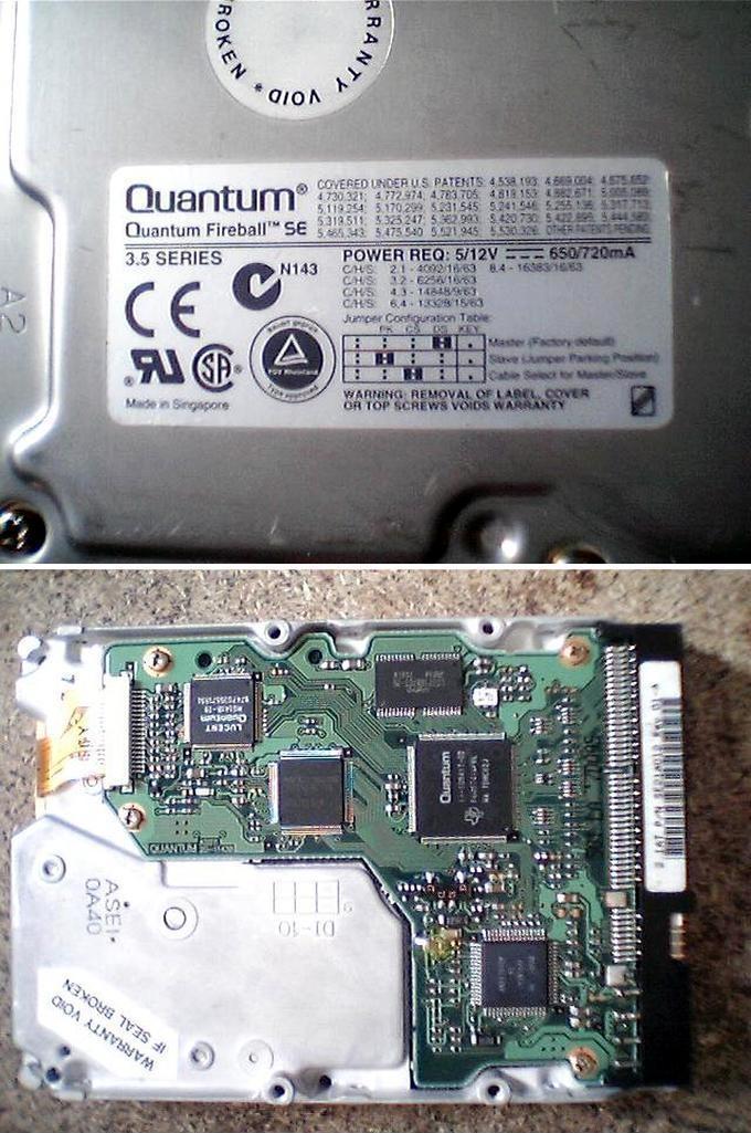
First HDD – "Quantum" of the "Fireball TM" family with drive chip TDA5147AK ( Fig.2). Let's see what he is like.

The top cover is secured with 4 screws in the corners and one screw and nut located on top, under the stickers. After removing the cover, the hard drive itself, the read heads and the magnetic head position control system are visible ( Fig.3). We disconnect the cable, unscrew the magnetic system (here you will need a specially sharpened hex key “asterisk”). If desired, the disk can also be removed by unscrewing the three screws on the motor spindle (a hex key is also needed).

Now we put the cover in place so that we can turn the HDD over for experiments with electronics and apply +5 V and +12V voltage to the power connector. The motor accelerates, runs for about 30 seconds, and then stops (there is a green LED on the circuit board - it lights up when the motor rotates and blinks when it stops).
The datasheet for the TDA5147K chip is easily found on the Internet, but it was not possible to figure out the rotation enable/disable signal using it. When “pulling up” the POR signals to the power buses, it was not possible to achieve the desired reaction, but when viewing the signals with an oscilloscope, it turned out that when the probe touches the 7th pin of the TDA5147AK chip, it resets and restarts the engine. Thus, having assembled the simplest short pulse generator ( Fig.4, bottom photo) with a period of several seconds (or tens of seconds), you can make the engine rotate more or less constantly. The resulting pauses in power supply last about 0.5 seconds and this is not critical if the motor is used with a light load on the shaft, but in other cases it may be unacceptable. Therefore, although the method is effective, it is not entirely correct. But it was never possible to launch it “correctly”.

Next HDD – "Quantum" of the "Trailblazer" family (Fig.5).

When the supply voltage is applied, the drive does not show any signs of life and the microcircuit 14-107540-03 on the electronics board begins to get very hot. There is a noticeable bulge in the middle of the microcircuit body ( Fig.6), which indicates its obvious inoperability. It's a shame, but not scary.

We look at the motor rotation control chip ( Fig.7) - HA13555. It does not heat up when power is applied and there is no visible damage to it. The tester's testing of the "piping" elements did not reveal anything special - all that remains is to figure out the "switching on" circuit.
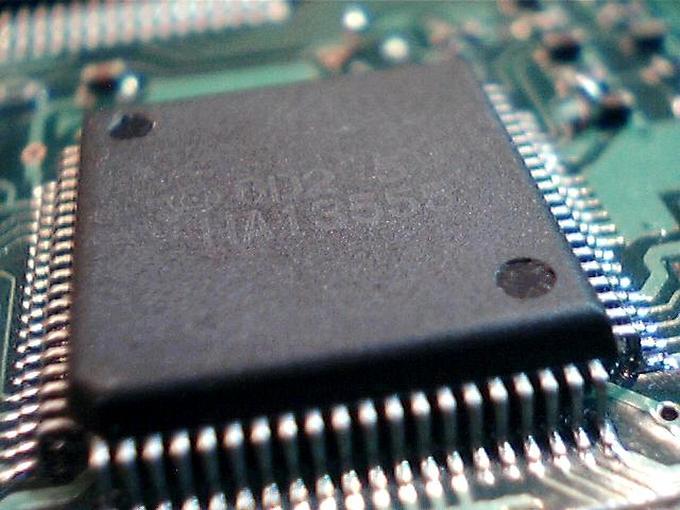
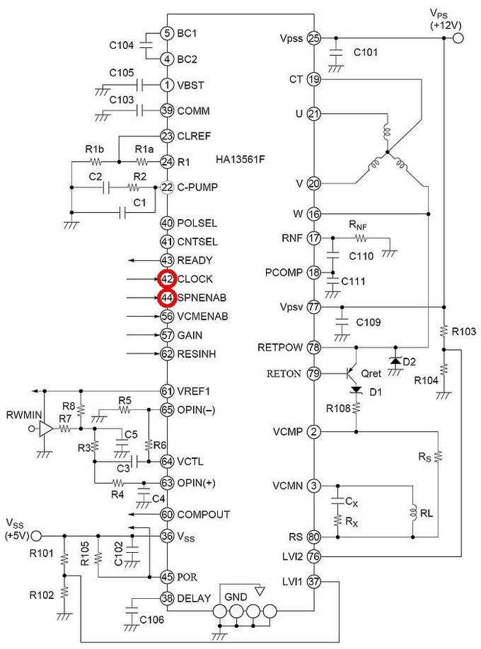
Search engines do not find datasheets for it, but there is a description for HA13561F. It is made in the same case, matches the power legs and “output” pins with the HA13555 (the latter has diodes soldered to the motor power conductors - protection against back-EMF). Let's try to determine the necessary control outputs. From the datasheet on HA13561F ( Fig.8) it follows that pin 42 (CLOCK) must be supplied with a clock frequency of 5 MHz with a TTL logic level and that the signal allowing the engine to start is a high level at pin 44 (SPNENAB).
Since microcircuit 14-107540-03 is not working, we cut off the +5 V power supply from it and from all other microcircuits except HA13555 ( Fig.9). Using a tester, we check the correctness of the “cuts” by the absence of connections.
In the bottom photo figure 9 The red dots show the places where the +5 V voltage is soldered for the HA13555 and the pull-up resistor of its 44 pins. If the resistor from pin 45 is removed from its original place (this is R105 according to Figure 8) and place it vertically with some inclination to the microcircuit, then an additional resistor for pulling up pin 44 to the “plus” can be soldered to the via hole and to the hanging pin of the first resistor ( Fig.10) and then +5 V power can be supplied to the place where they are connected.

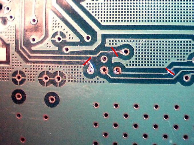
On the reverse side of the board, the tracks should be cut, as shown in Figure 11. These are “former” signals coming from the burned-out microcircuit 14-107540-03 and the old “pull-up” resistor R105.
You can organize the supply of “new” clock signals to pin 42 (CLOCK) using an additional external generator assembled on any suitable chip. In this case, K555LN1 was used and the resulting circuit is shown in Figure 12.

After “throwing” the +5 V supply voltage with the MGTF wire directly from the connector to pin 36 (Vss) and other required connections ( Fig.13), the drive starts and runs non-stop. Naturally, if the 14-107540-03 microcircuit were in good working order, all the modification would consist only of “tightening” the 44th pin to the +5 V bus.

This "screw" was used to test its performance at other clock frequencies. The signal was supplied from an external square-wave generator and the minimum frequency at which the drive operated stably was 2.4 MHz. At lower frequencies, acceleration and stopping occurred cyclically. The maximum frequency is about 7.6 MHz; with its further increase, the number of revolutions remained the same.
The number of revolutions also depends on the voltage level at pin 41 (CNTSEL). There is a table in the datasheet for the HA13561F chip and it corresponds to the values obtained from the HA13555. As a result of all manipulations, it was possible to obtain a minimum engine rotation speed of about 1800 rpm, and a maximum speed of 6864 rpm. The control was carried out using a program, an optocoupler with an amplifier and a piece of electrical tape glued to the disk so that when the disk rotates it overlaps the optocoupler window (the pulse repetition rate is determined in the spectrum analyzer window and then multiplied by 60).
Third drive - "SAMSUNG WN310820A".
When power is applied, the driver chip - HA13561 begins to get very hot, the motor does not rotate. There is a noticeable bulge on the chip body ( Fig.14), as in the previous case. It will not be possible to carry out any experiments, but you can try to power the motor from a board with the HA13555 chip. Long thin conductors were soldered to the motor cable and to the output contacts of the electronics board connector - everything started up and worked without problems. If the HA13561 were intact, the modification for the launch would be the same as for the Quantum Trailblazer (pin 44 to the +5 V bus).

Fourth drive - "Quantum" of the "Fireball SE" family with drive chip AN8426FBP ( Fig.15).
If you disconnect the head unit cable and apply power to the HDD, the engine picks up speed and, naturally, stops after a while. The datasheet for the AN8426FBP chip is available online and you can use it to figure out that pin 44 (SIPWM) is responsible for startup ( Fig.16). And if you now cut the track coming from the 14-108417-02 microcircuit and “pull up” pin 44 through a 4.7 kOhm resistor to the +5 V bus, then the engine will not stop.

And finally, going back a little, the waveforms were taken at pins W and V of the HA13555 chip relative to the common wire ( rice. 17).

The simplest practical use of an old HDD is a small emery for straightening drills, knives, screwdrivers ( Fig.18). To do this, just stick sandpaper on the magnetic disk. If the “screw” had several “pancakes”, then you can make replaceable disks of different grain sizes. And here it would be nice to be able to switch the rotation speed of the spindle motor, since with a large number of revolutions it is very easy to overheat the surface being sharpened.

Emery, of course, is not the only use for an old HDD. Designs for vacuum cleaners and even a machine for making cotton candy can easily be found online...
In addition to the text, there are the mentioned datasheets and files of printed circuit boards of external pulse generators in the program format of the 5th version (view from the printing side, the microcircuits are installed as SMD, i.e. without drilling holes).
Andrey Goltsov, r9o-11, Iskitim, April 2018.
List of radioelements
| Designation | Type | Denomination | Quantity | Note | Shop | My notepad | |
|---|---|---|---|---|---|---|---|
| To picture No. 4 | |||||||
| DD1 | Chip | K561LN2 | 1 | To notepad | |||
| R1, R2 | Resistor | 470 kOhm | 2 | smd 0805 | To notepad | ||
| R4 | Resistor | 10 kOhm | 1 | smd 0805 | |||


