ECU (electronic control unit) is a device that monitors the parameters of mechanisms during operation. Typically, the abbreviation ECU is used to refer to the engine control unit.
In fact, the car also has brake system control units (ABS unit), a body control unit, which is often called the Body Control Module (BCM or BSI), a climate control unit (climate control) and others.
Principle of operation
The operating principle of the electronic engine control unit is based on a standard microcontroller architecture. Data about engine parameters from various sensors enters the ECU and is then processed (amplified, digitized, encoded).
The main data processing according to a certain algorithm is performed by a microprocessor, which sends signals to actuators via the output bus. These signals are adapted (converted from digital to analog, amplified) and sent to the connectors of the electronic control unit.
The tasks solved by the electronic engine control unit include diagnostics of the operation of the main components. Modern ECUs can detect a variety of errors:
- lack of supply voltage at the electronic components of the engine or reduced power supply;
- open circuit or short circuit;
- incorrect signals at the output of sensors;
- misfires and injection;
- mismatch of ignition angles;
- and many others.
Errors are stored in non-volatile memory until they are deleted using diagnostic devices (current errors cannot be deleted without eliminating the cause of the error).
In cars of earlier years of production, errors could be removed by temporarily (about 15 minutes) disconnecting the battery from the vehicle's on-board power supply.
The ECU, together with the immobilizer, blocks engine operation in the event of unauthorized access. Each electronic engine control unit performs this function in accordance with the algorithm laid down by the manufacturer.
The following can be blocked:
- ignition signal to the coil;
- fuel injection pulses;
- permission to start the starter, etc.
In some vehicles, the engine may start for a few seconds and then stall.
Scheme
The electrical circuit diagram of the engine control unit itself is a production secret, and finding it even for domestic cars is very problematic.
Therefore, ECU repairs are carried out only by high-level professional electronics engineers. Typically, injection and ignition control transistors and reference voltage stabilizers in control units fail, and the firmware fails.
Specialists sometimes specifically change the firmware in order to increase engine response or reduce fuel consumption.
Video - M74 ECU firmware:
To repair electronic engine components, an electrical circuit for connecting the ECU is required. Such a diagram can be found in vehicle operation and repair manuals, software and hardware systems such as AUTODATA and TOLERANCE.
For example, consider the organization of the engine control circuit of a 2001 Volksvagen Golf 3, AEE engine, Magneti Marelli 1 AV control unit.

Without delving into the diagram, you can see that the ECU uses signals from the camshaft, mass air flow, coolant temperature, and oxygen sensors as sensors.
The signal coming from the camshaft sensor has the form:

As actuators, the ECU controls the injection signals of injectors, throttle valve drive, and ignition to the coil switch:

The ECU is connected to the immobilizer and the dashboard.
In order to check the electrical connections of the circuit components with the electronic engine control unit, you need to know the location of the contact pins (pinout), which is also given in the reference books:

Where is the engine control unit located?
In cars up to the 90s, the most rational location for the engine control unit was considered to be the space in the car interior near the left or right A-pillar in the area of the passenger’s or driver’s feet. First of all, it was believed that these were the most protected places from the point of view of mechanical damage and moisture penetration.
Video - transfer of the ECU on Kalina:
Since the mid-90s, engine control units have been installed in the engine compartment. This is due to the following considerations:
- under the hood it is easier to troubleshoot electrical connections;
- all communications with engine sensors and actuators become shorter and therefore more reliable;
- ECUs are now more reliably protected from moisture using special sealants.
In the absence of reference books, it is not difficult to find the electronic engine control unit by moving along the large wiring harness of the engine control system. It usually represents a small electronic unit in a metal casing with one or more connectors at the end.

In many cases, gaining access to the internal space of the unit and the electrical circuit is not easy: it is filled with compounds that need to be removed. The board usually contains a small number of components.

Symptoms of ECU malfunction
There is an opinion among auto electricians that the electronic engine control system is the last thing to fail. Moreover, they cannot always determine malfunctions of the engine control unit.
Indeed, the ECU can diagnose components connected to it, but in most cases it is not able to diagnose its own performance.
What may indicate a faulty ECU?
The most common sign of a malfunction is the constant blowing of fuses serving the engine control unit. In practice, there are frequent cases of reversal of the battery connection. The ECU circuit has protective diodes for this case. If they break through, a short circuit occurs in the power supply, which leads to constant blowing of fuses. Defective ones must be replaced.
Also, a power failure can cause the battery to shut down while the engine is running. In this case, the control unit is powered only from the generator and, if it is faulty, a situation may arise where the voltage is incorrectly supplied to the unit.
You cannot remove the battery terminals (!) while the engine is running., as many car enthusiasts do when starting from someone else’s battery.
How to check the ECU for performance
The first stage of performance testing is monitoring all supply voltages.
The second stage is computer diagnostics. If the diagnostic device communicates with the engine, this is already a sign that the ECU is working.
If the block is blocked by the immobilizer, then you need to bind the keys.
In some cases, to determine the malfunction, it is necessary to disassemble the computer, that is, remove the sealant and remove the cover, gaining access to the board. On it you can find burnt conductive paths, faulty transistors, diodes and other elements.
The most reliable way to check is to “toss” a known-good ECU. But it must either be immobilized or you will have to re-tie the keys and immobilizer.
Sometimes a set of ECU + immobilizer + key chip is sold at disassembly sites. In this case there is no problem. Connect the ECU and the immobilizer to the circuit, install the chip at the end of the pump coil on the ignition switch, and then start the engine.
Additional protection
To more reliably protect the engine control unit from battery polarity reversal, you can install diodes (preferably powerful zener diodes with a stabilization voltage of 15 - 17 Volts) along the supply circuits in reverse connection.
Then overvoltage and polarity reversal will lead to failure of the fuses serving the power supply circuits of the ECU; the increased voltage or voltage of reverse polarity will not pass to the control unit, and this is the biggest danger.
In order to protect the ECU from climatic influences, it is necessary to monitor the quality of the sealant. After five years of operation, it is advisable to take measures to improve the seal, since the old sealant may dry out under conditions of elevated temperatures under the hood.
Video - protection of the engine control unit of Renault Duster (Logan, Largus):
Do not block access to the unit with additional structures or place rags near it. This reduces the natural ventilation of the device, which heats up during vehicle operation.
Replacing the engine control unit
If the control unit is faulty and cannot be repaired, it should be replaced with a similar one with the same number indicated on the ECU housing.
Sometimes a slight deviation in the number is allowed. For example, a change in the last two or three digits may indicate a different engine size or modification, which may have virtually no effect on the technical characteristics.


The article will describe the pinout of the VAZ 2114 ECU and discuss all the modifications and features of this device. As you understand, any modern car is a whole arsenal of sensors and mechanisms. And they allow you to squeeze maximum power out of the engine without changing its volume. In order to independently repair electronics or carry out firmware, you need to know what a control unit is and on what principles it operates.
Where is the VAZ 2114 ECU located?
The block is located in the dashboard, directly under the tidy. To replace or dismantle, you need to unscrew the screws and remove the panel from the side, on the passenger side. Through the resulting hole you can see the ECU housing - it is installed inside a steel retainer.
To remove the electronic control unit, you need to unscrew the bolt and carefully pull out the housing, grasping the latch. Of course, it is necessary to turn off the power from the on-board network, otherwise expensive equipment can be damaged. A short circuit is the enemy of any electrical appliance, so be careful. It is advisable not only to remove ground from the battery, but also to disconnect the positive wire.
How does the ECU work?
At the heart is a microprocessor, which is responsible for the normal functioning of all key devices. On a VAZ 2114 car, the ECU collects data from sensors:
- Vehicle speed.
- Detonations.
- Lambda probe.
- DPKV.
- Air flow.
- TPDZ.
- Phases of injection of the air-fuel mixture.
- Coolant temperatures.
These are reading devices that collect information about the operation of an internal combustion engine. Why does he collect it? It is correct to divide and conquer by the following actuators:
- Fuel supply system (pump, injectors).
- Ignition system.
- Adsorber.
- Ventilation.
- Idle air control (yes, yes, this is not a sensor, but an actuator, no need to be confused).
- Automatic diagnostics.
The block diagram of the electronic control unit on the VAZ 2114 consists of three cascades, each of which has its own memory modules:
- A RAM unit (random access memory) is a system that has short-term memory. It stores all information about errors that occurred during operation during the current engine start. When the ignition is turned off (and the computer is de-energized), all memory is cleared and filled again the next time it starts.
- PROM is a programmable read-only memory device. This is the block in which the fuel map (firmware) of the electronic control unit is stored. It also permanently stores information about all system calibration results. And most importantly, this memory contains the algorithm of the internal combustion engine control system. This memory is permanent and is not erased even if the on-board network is completely disconnected. It is this block that is programmed when the “firmware” procedure is performed to improve the characteristics of the VAZ 2114 car.
- And the last block is the ERPZU. The memory unit is necessary to ensure the normal operation of the anti-theft system on the car. It stores passwords and encodings. Starting the engine is possible only if the data exchanged between the immobilizer and the EEPROM matches.
Repair and diagnostics of control units
The VAZ 2114 controller often breaks down. The system has a self-diagnosis function - the ECU queries all components and issues a conclusion about their suitability for operation. If any element fails, the “Check Engine” lamp will light up on the dashboard. It is possible to find out which sensor or actuator has failed only with the help of special diagnostic equipment. Even with the help of the famous OBD-Scan ELM-327, loved by many for its ease of use, you can read all engine operating parameters, find the error, eliminate it and delete it from the memory of the VAZ 2114 ECU.
Of course, it is wrong to simply delete errors. Be careful, because malfunctions don’t just appear. A good example is that a friend’s oxygen sensor broke down. And every other day he cuts down the mistake so that “it doesn’t become an eyesore.” But the reason lies in a faulty lambda. But what to do if the ECU does not want to respond to the scanner at all? Then check the following:
- Is there any mechanical damage to the housing, including oxidation and corrosion?
- The fuse is working properly, there is voltage and a connection to the power supply minus.
- Is the device overheating?
It is unlikely that you will be able to repair the control unit yourself; the work is too delicate. You can only replace it with a new one with your own hands.
Types of ECU VAZ 2114
The car was produced for more than 10 years, constantly improved, the characteristics became better and better. Of course, this was achieved through the use of new motors, sensors, and actuators. And most importantly, thanks to the installation of control units, whose operating speed is much higher (you have all heard about the frequency of processors; it is on this parameter that the characteristics of internal combustion engines depend today).
January-4 and GM-09
Until 2003, these electronic units were installed. They had a very wide range of models, the main difference between them was the presence or absence of a resonant-type knock sensor. The price of a VAZ 2114 ECU of the “January-4” type is no more than 6,000 rubles. The list of modifications is given in the table:
| 21114-1411020-22 | January-4, without oxygen sensor, RSO, 1st production version |
| 21114-1411020-22 | January-4, without oxygen sensor, RSO, 2nd production version |
| 21114-1411020-22 | January-4, without oxygen sensor, RSO, 3rd serial version |
| 21114-1411020-22 | January-4, without oxygen sensor, RSO, 4th production version |
| 21114-1411020-20 | GM,GM_EFI-4,2111 with oxygen sensor, USA-83 |
| 21114-1411020-21 | GM,GM_EFI-4,2111 with oxygen sensor, EURO-2 |
| 21114-1411020-10 | GM,GM_EFI-4,2111 with oxygen sensor |
| 21114-1411020-20h | GM, RSO |
Electronic control units ITELMA 5.1, January 5.1.X, Bosch M1.5.4
These ECUs belong to the next generation, they were successfully used on cars of models 2113 and 2115. If you are the owner of a VAZ 2114 car, which was released in 2013 or later, then the method of injection of the fuel-air mixture can distinguish it from its relatives: phased, pair-parallel or simultaneous. In general, all three ECUs (January, Bosch and Itelma) are complete analogues of each other. Modifications “January” and ITELMA:
Modifications of BOSCH electronic control units:
On VAZ 2114 cars produced in 2003-2007, you can most often find “January-5.1.1”. The price of such a block ranges from 7000-8000 rubles. On export versions of cars, as a rule, a Bosch brain was installed, the price of which was the same.
"January-7.2", Bosch M-7.9.7
The modification on the seventh of January depends on the engine size. Control units produced by BOSCH were installed only on those cars that were exported (they met the EURO-3 eco-standard). One and a half liter eight-valve engines were equipped with the following ECUs:
| 21114-1411020-80 | BOSCH-7.9.7, E-2.1.5 liters, 1st serial version. |
| 21114-1411020-80h | BOSCH-7.9.7, E-2.1.5 liters, tuning |
| 21114-1411020-80 | BOSCH-7.9.7+, E-2.1.5 liters, |
| 21114-1411020-80 | BOSCH-7.9.7+, E-2.1.5 liters, |
| 21114-1411020-30 | BOSCH-7.9.7, E-3.1.5 liters, 1st serial version. |
| 21114-1411020-81 | JANUARY_7.2, E-2.1.5 liters, 1st_serial version, unsuccessful, replacement_A203EL36 |
| 21114-1411020-81 | JANUARY_7.2, E-2.1.5 liters, 2nd_serial_version.unsuccessful, replacement_A203EL36 |
| 21114-1411020-81 | JANUARY_7.2, E-2.1.5 liters, 3rd_serial_version |
| 21114-1411020-82 | ITELMA, with acid sensor, E-2,1,5 liter, 1st_version |
| 21114-1411020-82 | ITELMA, with acid sensor, E-2,1,5 liter, 2nd_version |
| 21114-1411020-82 | ITELMA, with acid sensor, E-2,1,5 liter, 3rd_version |
| 21114-1411020-80h | BOSCH_797, without acid sensor, E-2, din., 1.5 liters |
| 21114-1411020-81h | JANUARY_7.2, without acid sensor, CO, 1.5 liter |
| 21114-1411020-82h | ITELMA, without acid sensor, CO, 1.5 liter |
For 1.6 liter engines:
| 21114-1411020-30 | BOSCH_797,E-2,1.6L,1st_series (software glitches) |
| 21114-1411020-30 | BOSCH_797,E-2,1.6L,2nd_series |
| 21114-1411020-30 | BOSCH_797+,E-2,1.6L,1st_series |
| 21114-1411020-30 | BOSCH_797+,E-2,1.6L,2nd_series |
| 21114-1411020-20 | BOSCH_797+,E-3,1.6L,1st_series |
| 21114-1411020-10 | BOSCH_797,E-3,1.6L,1st_series |
| 21114-1411020-40 | BOSCH_797,E-2,1.6L |
| 21114-1411020-31 | JANUARY_7.2, E-2, 1.6L, 1st_series (unsuccessful) |
| 21114-1411020-31 | JANUARY_7.2, E-2, 1.6L, 2nd_series |
| 21114-1411020-31 | JANUARY_7.2, E-2, 1.6L, 3rd_series |
| 21114-1411020-31 | JANUARY_7.2+, E-2, 1.6L, 1st_series, new_hardware.version. |
| 21114-1411020-32 | ITELMA_7.2,E-2,1.6L,1st_series |
| 21114-1411020-32 | ITELMA_7.2,E-2,1.6L,2nd_series |
| 21114-1411020-32 | ITELMA_7.2,E-2,1.6L,3rd_series |
| 21114-1411020-32 | ITELMA_7.2+, E-2, 1.6L, 1st_series, new_hardware.version. |
| 21114-1411020-30CH | BOSCH_with acid sensor, E-2, din, 1.6L |
| 21114-1411020-31CH | JANUARY_7.2, without acid sensor, CO, 1.6 liter. |
 The newest modification is the electronic control unit JANUARY-7.3, with its help the control system of eight-valve 1.6-liter engines, which were produced since 2007, was organized. Modifications January-7.3 could comply with EURO-3 and 4 eco-standards, produced by the AVTEL and ITELMA plants .
The introduction of electronics into the design of a car engine has led to the fact that the operation of the engine is controlled by the electronic engine control unit ECU (). Modules of this type are also called controllers. The gasoline or diesel engine, as well as other vehicle systems, are controlled through special control units. There are several types of them and they all have their own connection scheme to the on-board electronics.
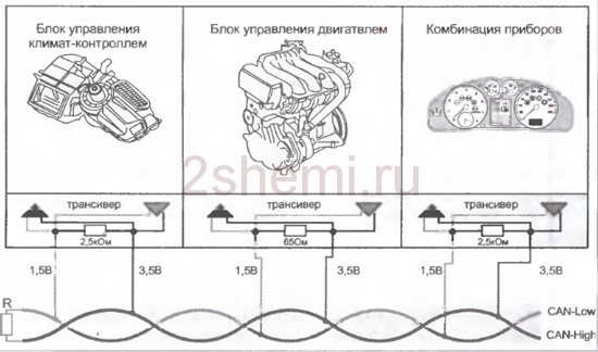
The electronic engine control unit maintains a constant and continuous exchange of data with control modules of other systems. Data streams are transmitted via a special CAN bus. Through this bus, an effective integration of all electronic digital systems of the vehicle is realized, which ultimately represents a single on-board network. Below is a guide to all the most common ECUs.
Pinout of ECU connectors VAZ January
Scheme January 5.1

Scheme January 7.2

Pinout January 7, BOSCH M7.9.7, M 73
| № | 8V | 16V | № | 8V | 16V | |
| 1 | Cat. ignition 2 c. | 42 | Rough road sensor signal input (3) | |||
| 2 | Ignition cat 2-3 c. | Cat. ignition 3 c. | 43 | |||
| 3 | Weight cat. light up | Weight cat. light up | 44 | |||
| 4 | Cat. ignition 4 c. | 45 | Phase sensor power output (2) | |||
| 5 | Ignition cat 1-4 c | Cat. ignition 1 c. | 46 | Canister valve control output (1) | ||
| 6 | Injector 2 | 47 | Injector 4 | |||
| 7 | Injector 3 | 48 | Heater control DK1 (D) | |||
| 8 | Tachometer output | 49 | ||||
| 9 | 50 | Controlling the additional starter relay | ||||
| 10 | Fuel consumption signal | 51 | Weight | |||
| 11 | 52 | |||||
| 12 | Power supply +12 V. Battery (ignition switch 30 contacts) | 53 | Weight | |||
| 13 | +12 V. Ignition (deputy ignition 15 contacts) | 54 | ||||
| 14 | Main relay control output | 55 | Oxygen sensor 2 signal input (A) | |||
| 15 | Crankshaft sensor input (A) | 56 | ||||
| 16 | Throttle sensor signal input (C) | 57 | Switching calibrations, short to ground | |||
| 17 | Throttle sensor ground (B) | 58 | ||||
| 18 | Oxygen sensor 1 signal input (A) | 59 | Speed sensor signal input.(2) | |||
| 19 | Knock sensor signal input (1) | 60 | ||||
| 20 | Knock sensor weight (2) | 61 | Weight | |||
| 21 | 62 | |||||
| 22 | 63 | +12V power input after main relay | ||||
| 23 | 64 | Idle Speed Control (D) | ||||
| 24 | 65 | Idle Speed Control (C) | ||||
| 25 | 66 | Idle Speed Control (B) | ||||
| 26 | 67 | Idle Speed Control (A) | ||||
| 27 | Injector 1 | 68 | Fan relay control output 1 O.Zh. | |||
| 28 | Oxygen Sensor Heater 2 (D) | 69 | Air conditioner relay control output | |||
| 29 | Fan control output 2 O.Zh. | 70 | Fuel pump relay control output | |||
| 30 | 71 | K-Line | ||||
| 31 | Check lamp | 72 | ||||
| 32 | Power output +5V DPDZ(3), DND(1) | 73 | ||||
| 33 | Power output +5V DMRV (4) | 74 | ||||
| 34 | Crankshaft sensor signal input (1) | 75 | Air conditioner request signal | |||
| 35 | Mass of sensors. | 76 | Request to turn on the power steering. | |||
| 36 | Mass of sensors. | 77 | ||||
| 37 | Air flow sensor signal input (5) | 78 | ||||
| 38 | 79 | Phase sensor signal input (3) | ||||
| 39 | Coolant sensor signal input (2) | 80 | Weight | |||
| 40 | Signal input. DTVV. (DFID pin. 1) | 81 | ||||
| 41 | ||||||

Connecting the K-line adapter

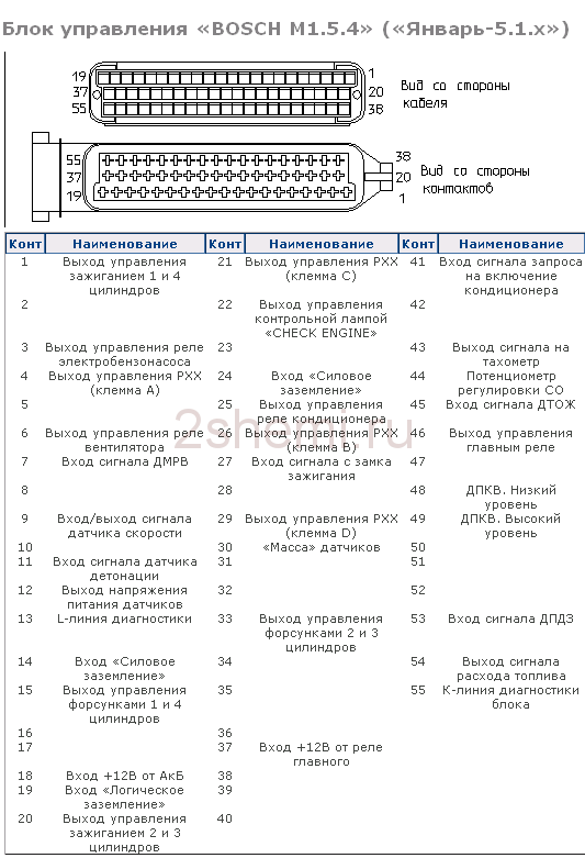
Pinout of VAZ Bosch ECU connectors
Bosch 7.9.7 January 7.2

| Number | Bosch M1.5.4 (1411020 and 1411020-70) January 5.1.1 (71) |
Bosch M1.5.4 (40/60) January-5.1 (41/61) January 5.1.2 (71) |
Bosch MP7.0 |
| 1 | Ignition 1-4 cylinders. | Ignition 1-4 cylinders. | Ignition 1-4 cylinders. |
| 2 | . | Ground ignition wire. | . |
| 3 | Fuel pump relay | Fuel pump relay | Fuel pump relay |
| 4 | Stepper motor PXX(A) | Stepper motor PXX(A) | Stepper motor PXX(A) |
| 5 | Canister purge valve. | Canister purge valve. | |
| 6 | Cooling fan relay | Left fan relay (only on Nivas) | |
| 7 | Air flow sensor input signal | Air flow sensor input signal | |
| 8 | . | Phase sensor input signal | Phase sensor input signal |
| 9 | Speed sensor | Speed sensor | Speed sensor |
| 10 | . | General. Oxygen sensor weight | Oxygen sensor weight |
| 11 | Knock sensor | Knock sensor | Knock sensor input 1 |
| 12 | Power supply for sensors. +5 | Power supply for sensors. +5 | Power supply for sensors. +5 |
| 13 | L-line | L-line | L-line |
| 14 | Weight of injectors | Weight of injectors | Weight of injectors. Power "ground" |
| 15 | Control of injectors 1-4 | Oxygen sensor heater | Check Engine Light |
| 16 | . | Injector 2 | Injector 3 |
| 17 | . | Recirculation valve | Injector 1 |
| 18 | Power supply +12V non-switchable | Power supply +12V non-switchable | Power supply +12V non-switchable |
| 19 | Common wire. Weight of electronics | Common wire. Weight of electronics | |
| 20 | Ignition 2-3 cylinders | Ignition 2-3 cylinders | |
| 21 | Stepper motor PXX(C) | Stepper motor PXX(C) | Ignition 2-3 cylinders |
| 22 | Check Engine Light | Check Engine Light | Stepper motor PXX(B) |
| 23 | . | Injector 1 | Air conditioner relay |
| 24 | Stepper motor weight | Weight of stepper motor output stages | Power grounding |
| 25 | Air conditioner relay | Air conditioner relay | . |
| 26 | Stepper motor PXX(B) | Stepper motor PXX(B) | Weight of sensors TPS, DTOZH, DMR |
| 27 | Ignition switch terminal 15 | Ignition switch terminal 15 | Ignition switch terminal 15 |
| 28 | . | Oxygen sensor input | |
| 29 | Stepper motor PXX(D) | Stepper motor PXX(D) | Oxygen sensor 2 input signal |
| 30 | Weight of sensors MAF, DTOZH, DPS, DD, DPKV | Knock sensor input 2 | |
| 31 | . | Reserve output high current | Rough road sensor input signal |
| 32 | . | . | Fuel consumption signal |
| 33 | Control of injectors 2-3 | Oxygen sensor heater. | . |
| 34 | . | Injector 4 | Injector 4 |
| 35 | . | Injector 3 | Injector 2 |
| 36 | . | Exit. Intake pipe length control valve. | Main relay |
| 37 | Nutrition. +12V after the main relay | Nutrition. +12V after the main relay | |
| 38 | . | Low-current backup output | . |
| 39 | . | . | Stepper motor IAC (C) |
| 40 | . | Reserve input discrete high | . |
| 41 | Request to turn on the air conditioner | Oxygen sensor heater 2 | |
| 42 | . | . | |
| 43 | Signal to tachometer | Signal to tachometer | Signal to tachometer |
| 44 | CO - potentiometer | Air temperature sensor | . |
| 45 | Coolant temperature sensor | Coolant temperature sensor | |
| 46 | Main relay | Main relay | Cooling fan relay |
| 47 | Programming permission | Programming permission | Air conditioner request signal input |
| 48 | Crankshaft position sensor. Low level | Crankshaft position sensor. Low level | |
| 49 | Crankshaft position sensor.High level | Crankshaft position sensor.High level | |
| 50 | . | Recirculation valve position sensor | Programming permission |
| 51 | . | Request to turn on the power steering | DC heater |
| 52 | . | Reserve input discrete low | . |
| 53 | Throttle position sensor | Throttle position sensor | |
| 54 | Fuel consumption signal | Fuel consumption signal | Stepper motor IAC (D) |
| 55 | K-line | K-line | K-line |
Modifications of electronic control units for VAZ cars
The modification on the seventh of January depends on the engine size. Control units produced by BOSCH were installed only on those cars that were exported (they met the EURO-3 eco-standard). For 1.5l 8 cl. the motors were equipped with the following ECUs:
| 21114-1411020-80 | BOSCH-7.9.7, E-2.1.5 liters, 1st serial version. |
| 21114-1411020-80h | BOSCH-7.9.7, E-2.1.5 liters, tuning |
| 21114-1411020-80 | BOSCH-7.9.7+, E-2.1.5 liters, |
| 21114-1411020-80 | BOSCH-7.9.7+, E-2.1.5 liters, |
| 21114-1411020-30 | BOSCH-7.9.7, E-3.1.5 liters, 1st serial version. |
| 21114-1411020-81 | JANUARY_7.2, E-2.1.5 liters, 1st_serial version, unsuccessful, replacement_A203EL36 |
| 21114-1411020-81 | JANUARY_7.2, E-2.1.5 liters, 2nd_serial_version.unsuccessful, replacement_A203EL36 |
| 21114-1411020-81 | JANUARY_7.2, E-2.1.5 liters, 3rd_serial_version |
| 21114-1411020-82 | ITELMA, with acid sensor, E-2,1,5 liter, 1st_version |
| 21114-1411020-82 | ITELMA, with acid sensor, E-2,1,5 liter, 2nd_version |
| 21114-1411020-82 | ITELMA, with acid sensor, E-2,1,5 liter, 3rd_version |
| 21114-1411020-80h | BOSCH_797, without acid sensor, E-2, din., 1.5 liters |
| 21114-1411020-81h | JANUARY_7.2, without acid sensor, CO, 1.5 liter |
| 21114-1411020-82h | ITELMA, without acid sensor, CO, 1.5 liter |
For 1.6 liter engines:
| 21114-1411020-30 | BOSCH_797,E-2,1.6L,1st_series (software glitches) |
| 21114-1411020-30 | BOSCH_797,E-2,1.6L,2nd_series |
| 21114-1411020-30 | BOSCH_797+,E-2,1.6L,1st_series |
| 21114-1411020-30 | BOSCH_797+,E-2,1.6L,2nd_series |
| 21114-1411020-20 | BOSCH_797+,E-3,1.6L,1st_series |
| 21114-1411020-10 | BOSCH_797,E-3,1.6L,1st_series |
| 21114-1411020-40 | BOSCH_797,E-2,1.6L |
| 21114-1411020-31 | JANUARY_7.2, E-2, 1.6L, 1st_series (unsuccessful) |
| 21114-1411020-31 | JANUARY_7.2, E-2, 1.6L, 2nd_series |
| 21114-1411020-31 | JANUARY_7.2, E-2, 1.6L, 3rd_series |
| 21114-1411020-31 | JANUARY_7.2+, E-2, 1.6L, 1st_series, new_hardware.version. |
| 21114-1411020-32 | ITELMA_7.2,E-2,1.6L,1st_series |
| 21114-1411020-32 | ITELMA_7.2,E-2,1.6L,2nd_series |
| 21114-1411020-32 | ITELMA_7.2,E-2,1.6L,3rd_series |
| 21114-1411020-32 | ITELMA_7.2+, E-2, 1.6L, 1st_series, new_hardware.version. |
| 21114-1411020-30CH | BOSCH_with acid sensor, E-2, din, 1.6L |
| 21114-1411020-31CH | JANUARY_7.2, without acid sensor, CO, 1.6 liter. |
Location of the ECU in VAZ cars

Ford ECU connector pinout diagram

Diagrams of other connectors of electronic control units


Renix ECU

ECU 2LT-E, KZN165, KZJ90


Passat ECU

Progress electronic control unit

Mitsubishi ECU
Nissan ECU

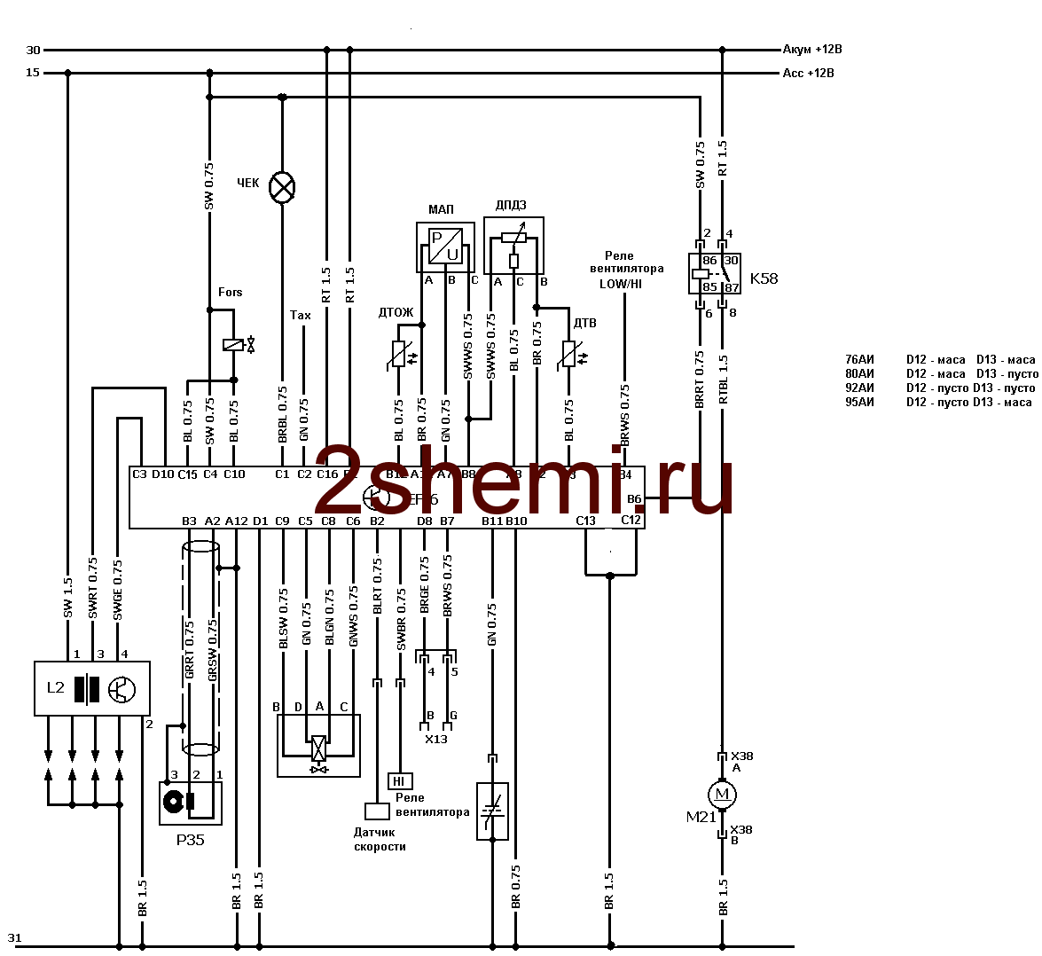
The UAZ Hunter engine includes an electronic control unit, sensors, actuating electric mechanisms, a diagnostic malfunction indicator lamp, a wiring harness, and a diagnostic connector. Diagrams of the engine control system are presented below.
Diagrams of the UAZ Hunter engine control system with MIKAS-7.2, BOSCH ME17.9.7, M1.5.4.U AUTRON units.
The UAZ Hunter models UAZ-315195 and UAZ-315196 with the ZMZ-409 engine were equipped with an integrated microprocessor control system with electronic control units, controllers, type M1.5.4.U AUTRON, MIKAS-7.2, BOSCH M17.9.7, BOSCH ME17.9.7 .
Diagram of the control system of the UAZ Hunter model UAZ-315195 with the ZMZ-409.10 Euro-0 engine and the M1.5.4.U AUTRON control unit.
Diagram of the engine control system of the UAZ Hunter model UAZ-315195 with the ZMZ-409.10 Euro-0 engine and the M1.5.4.U AUTRON or MIKAS-7.2 control unit.
Diagrams of the engine control system of the UAZ Hunter model UAZ-315195 with the ZMZ-409.10 Euro-2 engine and the MIKAS-7.2 control unit.
The composition, devices and components of the UAZ Hunter control system with the ZMZ-409.10 Euro-2 engine and the MIKAS-7.2 controller are discussed in the material.
Diagrams of the engine control system of the UAZ Hunter model UAZ-315195 with the ZMZ-40904.10 Euro-3 engine and the BOSCH ME17.9.7 control unit.
The composition, elements and components of the UAZ Hunter control system with the ZMZ-40904.10 Euro-3 engine and the BOSCH ME17.9.7 controller are discussed in the material.
Wiring harness diagram 315196-3724067 of the UAZ Hunter engine control system of the UAZ-315196 model with the ZMZ-4091.10 Euro-3 engine and the BOSCH M17.9.7 control unit.
The composition, sensors and actuators of the control system of the UAZ Hunter, model UAZ-315196, with the ZMZ-4091 Euro-3 engine and the BOSCH M17.9.7 unit are discussed in the material.
Wiring harness diagram 315195-3724067-62 of the UAZ Hunter engine control system of the UAZ-315195 model with the ZMZ-40905.10 Euro-4 engine and the BOSCH ME17.9.7 control unit.
The composition, sensors and actuators of the UAZ Hunter control system with the ZMZ-40905 Euro-4 engine and the BOSCH ME17.9.7 control unit are discussed in the material.
Designations of components and circuits in the diagrams:
A1 — engine control controller (unit);
A2 — fuel module with level sensor;
A3 - instrument cluster or panel;
A4 - immobilizer (car anti-theft system - APS);
A5 - route;
A6 — accelerator pedal module (E-gas);
A7 — throttle device with electric drive;
B1 - throttle position sensor;
B2 - mass air flow sensor;
B3 - coolant temperature sensor;
B4 - air temperature sensor;
B5 - knock sensor;
B6 - oxygen sensor No. 1;
B7 - oxygen sensor No. 2;
B8 - rough road sensor;
BP1 — intake air absolute pressure sensor;
BP2 - emergency oil pressure alarm sensor;
BP3 - air conditioner refrigerant pressure sensor;
BR1 — synchronization sensor (crankshaft position);
BR2 — phase sensor (camshaft position);
BV1 - vehicle speed sensor;
F1-F4 - spark plugs for cylinders 1-4;
FU1-FU6 - fuse;
HL1 - MIL lamp for engine diagnostics;
HL2 — IMMO status lamp (ALS unit);
GB1 - rechargeable battery;
KA1 - main relay;
KA2 - electric fuel pump relay;
KA3, KA4 - relay for electric fans No. 1 and No. 2 for engine cooling;
KA5 - air conditioning compressor clutch relay;
L1 – immobilizer transceiver antenna;
M1 - electric fuel pump;
M2, M3 - electric fans 1 and 2;
PF1 - tachometer;
PS1 - coolant indicator;
TV1, TV2 - two-terminal ignition coil;
TV3 - ignition module with two-terminal coils;
TV4-TV7 - individual ignition coils;
TV8 – four-terminal ignition coil;
W1-W4 - high-voltage ignition wires;
SA1 - ignition switch;
SA2—mass switch;
SA3 - air conditioner switch;
SA4 — two-channel brake pedal switch;
SA5 – clutch pedal switch;
XS1 — diagnostic connector;
XS2 — nozzle connector;
Y1-Y4 — gasoline injectors;
Y5 — additional air regulator (idle speed);
Y6 — adsorber purge valve;
Y7 - electric coupling of the air conditioning compressor;
* — the component can be installed as an additional kit.
Electrical circuits in the diagrams:
“15” - circuit from the ignition switch;
“30” - battery power circuit;
“Um” - power circuit from the main relay of the system;
“Ue” - power circuit from the electric fuel pump relay;
GNP - power ground of the controller output stages;
GNI - “ground” for power ignition channels;
GND - “ground” for the logical and digital circuits of the controller;
GNA - “ground” for the signal (analog) circuits of the controller.
The remaining circuits are named after the terminals of the electronic control unit.
It is not allowed to operate the ZMZ-409 UAZ Hunter engine with the diagnostic lamp on. Constant lighting of the lamp indicates the presence of malfunctions in the engine control system.
If there are malfunctions, the control system automatically switches to operation mode - starting, especially of a cold engine, worsens, toxicity and fuel consumption increase. It is necessary to diagnose the system and eliminate the malfunction as soon as possible.


